![]()
![]()
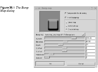
Bump Map
| |
|
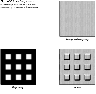
Bump Map works by embossing an image, and mapping this relief to another image. This will create a 3-D effect in the second image, just as if you had modeled it in clay. Bump Map And EmbossFirst read about Emboss in "Distort Filters" starting on page 459 to understand the concepts of Azimuth, Evaluation and Depth. There are many differences between Bump Map and the bumpmap option in the Emboss plug-in. First of all, in Emboss bumpmap, you can't specify a map image (see map image in Figure 36.2). The Bump Map plug-in has more options than Emboss, and you can bumpmap any type of image. Emboss only works for RGB images without alpha. How To Use Bump MapBecause you can bumpmap any image, you may have to adjust the position of the background bumpmap. To do so, use the X and Y offset slides. You may also want to compensate for the loss of luminance resulting from embossing by using the Compensate for darkening button. Because Emboss raises light pixels and carves dark pixels, it's quite simple to reverse so that otherwise dark and carved parts of your map will turn light and raised. To achieve this, check Invert bumpmap.
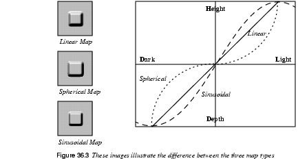
The Ambient slide controls the amount of ambient light in your image. A high level of ambient light will make all shadows disappear, and the raised and carved parts will be less apparent. Waterlevel only becomes relevant if there are alpha values or transparency in the map image. Transparent pixels in a map image will be treated as dark pixels, and therefore become carved. If you slide the Waterlevel up to 255, the transparent pixels will be flattened and turn invisible, just as if you had raised the water level in a pond. If you check the Invert bumpmap radio button, they will be treated as light pixels and get raised, but Waterlevel will flatten that, too. Linear map, Spherical map and Sinusoidal map are the three bumpmap types used to create a 3-D model. Figure 36.3 shows the relationship between different map modes, and how they raise/carve in relation to the luminance of the pixels.
| |
Coordinate Map
| |
 |
The Coordinate Map filter does the same thing as the Displace filter (described in the next section). The creator of this filter writes that Coordinate Map is easier to use, and maybe he's right -- you will have to try it for yourself. There is one limitation though, it will only work with 256x256 pixel images. Here is how it works: The plug-in will map two images (one in the horizontal direction, and one in the vertical direction) on a source image. The source image will get the architecture from the map images. Read about the Displace filter and you will understand the Coordinate Map filter, too. |
Displace
| |
|
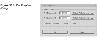
Displace is a general distort filter, which can be used for nearly all kinds of distortion. You can, for example, use it to whirl, pinch, shift, spread or melt your image. We will try to give you a short introduction to the hidden secrets of this filter. How Does It Work?It is clear that this filter will displace an image or part of an image; the question is how? To put it simply, the Displace filter needs a displacement map to tell it how to distort the image. The brightness or darkness values in this map control how Displace moves the image pixels. To make displacement easy, always use grayscale images as maps. It will work with colored images too, but as displacement depends on the brightness/darkness of the map, the color information is simply not used. Summary· Use grayscale images as displacement maps. · The amount of displacement is based on the brightness/darkness of CalculationsAs we know from earlier chapters, you can use 256 shades of gray in a grayscale image. How bright or dark a gray "color" is depends on the Intensity value, which goes from 1 (black) to 256 (white). In the middle of this range we find "medium gray," with a value of 128. One of the fundamental parts of displacement is that the "dark values" 0 to 127 will be displaced in one direction, the "medium gray" value 128 will not be displaced at all, and the "light values" 129 to 256 will be displaced in the opposite direction of the dark values. To make things easier we can put this range in a new perspective. If you think of -128 as total darkness, 0 as medium gray and +128 as total lightness, it becomes more clear that displacement will go in different directions, because we have negative and positive intensity in our map. The maximum displacement in either direction happens where the map has a value of either -128 or +128. Summary· Displacement is based on a brightness/darkness scale, ranging from -128 to +128. · There will be no displacement where the value is 0. · The displacement goes in two directions. Negative values displace in one direction, and positive values displace in the opposite direction. The User InterfaceLet's take a closer look at the user interface. As you can see, you can displace in both X and Y directions. You can also set how much you want to displace, and which map to use. To make it easy to understand, we will stick with only one direction (X in this case). The first thing you have to do is create or open the image to be displaced. (We will render a grid system so you can see what's happening.) The second thing you have to do is make a displacement map. The easiest way to do this is to duplicate your image ( Convert the duplicate to grayscale ( Summary· The map must have the same proportions as the image or selection that is going to be displaced. | |
 |
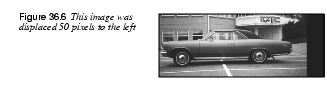
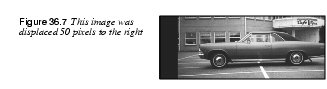
Example 1: Basic Displacing 1. To make it easy, copy, grayscale and clear the image that is going to be displaced, and use that as the base for a map. Now, bring up the Displacement plug-in from the image that is going to be displaced. 2. Uncheck "Y", make sure that "X" is checked and check Black. 3. Set the X displacement to 50, and bring up the map image. 4. Fill the map with white (+128), choose the name of the map image in the displacement dialog and press OK. The image has now been displaced 50 pixels to the left, as shown in Figure 36.6. 5. Now press Ctrl+z and do it again, but this time with a map that is totally black (-128). The image has now been displaced 50 pixels to the right, as shown in Figure 36.7 6. Let's do this with a map with a value of +64 (a gray with the Intensity value 191). This will displace the image 25 pixels to the left because (64 x 50)/128 is 25, which leads to the following algorithm: (value (of gray) x (displacement value))/128 equals the amount of displacement (Figure 36.8). 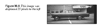
7. Positive values will displace to the left, and negative to the right. More examples: Gray value: -64 (dark) Displacement value: +50 -> (-64 x 50)/128 = -25 -> 25 pixels displacement to the right. Gray value: +64 and Displacement value: -50 -> (64 x -50)/128 = -25 -> 25 pixels displacement to the right. Summary· If you have positive "X" displacement values, a bright map will displace to the left and a dark to the right. · The amount of displacement is based on this algorithm: (value x displacement)/128 = displacement in pixels, positive to the left and negative to the right. · The above is also true for Y direction displacement, you just have to switch left to top and black to bottom. · If you have positive "Y" displacement values, a bright map will displace to the top of the image and a dark to the bottom of the image. · The amount of displacement is based on this algorithm: (value x displacement)/128 = displacement in pixels, positive to the top and negative to the bottom. Example 2: Displacing In Two DirectionsNow we move to more complex displacement. As you see in the dialog, you can displace in both X and Y directions. This means that you can, for example, displace the image towards the bottom-left corner. To achieve this, you have to make two maps, one white and one black. Map the black one to Y and the white one to X. Your image will now be displaced toward the bottom-left corner (Figure 36.9). 
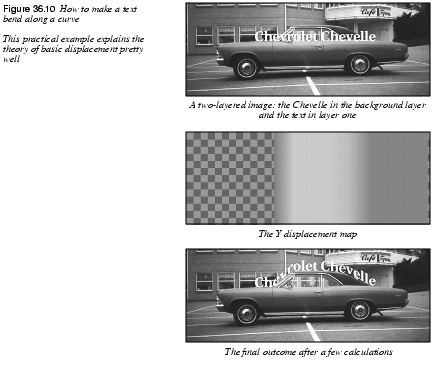
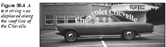
Examples 3 And 4: Spreading And CurvingWe said earlier that you can achieve any kind of distortment with this plug-in, so we will give you two more examples: Spread horizontal: Create a map made of horizontal black, white and gray stripes. The different intensities of the stripes will make the displaced image look as if you have spread it in horizontal ribbons. You have to experiment by yourself to figure out what you can do, but trust us -- you can do a lot with this plug-in. Curving Text: The obvious example is to bend text over something circular, such as a terrestrial globe. To achieve that, you'll have to create a suitable gradient (dark at both ends and light in the middle) with the Gradient Editor. In Figure 36.10 we have created a displacement map that will make the text flow around the shape of the car.
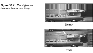
Using Transparency In Map ImagesSometimes, it's hard to create the kind of map you want, for example, when you only want to displace part of your image. When you experiment with different maps, you'll often want to darken/lighten them, but this will inevitably alter the medium gray value. The perfect 0 will be transformed to something that will displace your image. The way to get around this problem is to make the static parts of your map transparent, because fully transparent pixels are treated as if they had a value of 0. Black pixels, which are (almost) transparent, are treated as having a value of a bit under 0, or somewhere around (-5). The same goes for semi-transparent white pixels, but they will get a positive value around (+5), so alpha values should play a very important part in your map making. What Are Black, Smear And Wrap Good For?Say that you're using a white map, a displace value of 50 and that you only want to displace in the X direction. When the image is displaced 50 pixels to the left, there will be 50 pixels missing at the right side of the image. If you check Black, a black color will fill this part for you. If you check Smear, those 50 pixels will be stretched from the right part of the image. If you press Wrap, the 50 pixels you pushed out of the frame at the left side will appear at the right side of the image to cover for the missing pixels. How To Calculate Where A Pixel Will End UpLet's choose a pixel that is positioned at 50(x) and 50(y) in the image coordinate system.We go to our maps and check the Intensity value of the equivalent pixel in that position. In this case we presume that the Intensity value we got from map X (the horizontal displacement map) was 230, which means (230 - 128) = 102 in the displacement range. Map Y (the vertical displacement map) had an Intensity value of 55, which means (55 - 128) = -73 in the displacement range. We also choose a displacement value of 50 for X and 30 for Y. If we put these values in our algorithm. · (102 x 50)/128 = 39.84, which is the displacement of map X (the pixel will displace 40 pixels to the left). · (-73 x 30)/128 = -17.11, which is the displacement of map Y (the pixel will displace 17 pixels downwards). These calculations tell us that our pixel will end up at x=10 and y=67, i.e., the pixel will be moved a bit closer to the bottom-left corner. |
Fractal Trace
| |
|
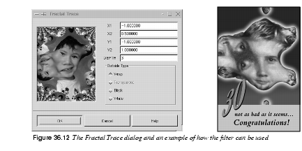
Fractal Trace distorts your image using a Mandelbrot fractal. It does this by mapping your image to the fractal, as in Figure 36.12 Fractal Trace And Fractal ExplorerFive parameters control the Mandelbrot fractal; X1, X2, Y1, Y2 and DEPTH. For a better understanding of these parameters, read about fractals in Fractal Explorer. X(Y)1 and X(Y)2 correspond to the X(Y)min and X(Y)max parameters in the main Fractal Explorer dialog, and DEPTH is the same as the ITER(ations) parameter. Note that the default value for DEPTH (3) is much lower in the Fractal Trace dialog than the default value for ITER in the Fractal Explorer dialog (50). If you increase the depth value, you'll map your image to a classic fractal shape, but this will yield less spectacular effects than using lower values (the opposite is true for Fractal Explorer). Outside TypeThis option lets you choose between four different backgrounds to cover up parts that were displaced by the fractal mapping. This works the same as the On Edges option in the Displace filter; read more about it in What Are Black, Smear And Wrap Good For?. Note that to be able to use the Transparent option, you have to have an alpha enabled image. To make it so, select | |
Illusion
| |
|
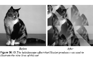
Illusion duplicates your image (x) times, and puts them in a circle around the center of the original image. The surrounding images are superimposed on the original, so it looks a bit blurry or ghostlike. The only option in this filter is how many (x) copies you want to apply to your image. Another word for this filter is kaleidoscope, which is a quite accurate description of what it does. | |
Make Seamless
| |
|
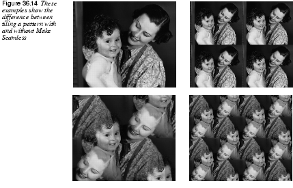
The Make Seamless plug-in prepares an image for tiling by creating seamless edges. This filter does away with all those ugly edges, and it's an easy way to create good-looking patterns. If you want to create a seamless pattern as a background for your desktop or in a web page, this is (often) the best tool to use. Note that the center of the original image will constitute the only focused part of the new image. Mirrors of the original image are placed in the center and in all four corners of the seamless image, and those mirrors blend together at the edges, causing it to look a bit blurred or double-exposed in those areas. If an important part of your image (like a face) is somewhere other than in the middle, you may have to do some correction work by copying parts of the original image and pasting them into the seamless image. If you feel that the result of this filter is too soft or blurred, try to correct your image with the Offset command in the Image menu. Read more about it in Offset.
| |
Map Object
| |
|
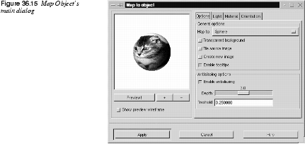
The Map Object filter will map your image to a sphere, a plane, a box or a cylinder. You can also apply different lighting effects to the mapped object to make it even more convincing. You can even specify the properties of the "material" in the mapped object by changing the values for intensity and reflectivity. This is a very nice plug-in for creating 3-D-effects in Gimp. You can, for example, create a perfect soccer ball. There are, of course, many more applications for this excellent plug-in -- the only limit is your imagination. Main InterfaceIn the main interface there is a preview window and tab for Options, Light, Material and Orientation. To be able to see what you're doing, you must first press the Preview button (there's no auto-preview because that would slow things down).
It is a good idea to use Show preview wireframe. Then, your object will be displayed as a wireframe, and you can see your actions take place in realtime. Whenever you need to take a good look, just press Preview. You can also zoom the preview by pressing + or -. OptionsYou can choose to map to a plane, a sphere, a box or a cylinder. If you choose to map your image to a box or a cylinder, a new tab will appear called Box and Cylinder. See Box And Cylinder for information on this folder. · Transparent background results in a transparent surrounding (the drawable will turn transparent outside of the object). · Tile source image means that the source image will be repeated or tiled to extend the map object (plane) into infinity. For example, if you map to a plane and this plane is tilted in some direction, there will be a lot of space around the output image. Instead of having this space filled by a background color or transparency, the plane will tile itself, filling the entire output image. · Create new image preserves the original image, creating a duplicate image where the filter takes effect. · Enable tooltips is a nice option. When you get to know the filter and already know what the tooltips are all about, you can disable the tooltip messages by unchecking this option. · The Enable Antialiasing option enables you to turn antialiasing on or off, but we recommend you use it; otherwise, the images will look very jagged and ugly (there can of course be moments when a non-antialiased image can be useful). Depth refers to the amount of antialiasing -- the higher the value, the better the antialiasing, but it will also be slower. Threshold determines the limit of antialiasing, the process is interrupted when the difference between pixels is lower than the value in the input field. 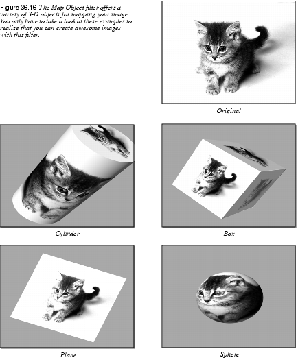
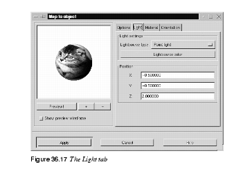
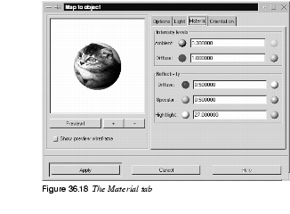
LightYou can set the type of light, the light color and the position of the light source, and if you have chosen Directional Light, you can also set the angle of the light source. Light SettingsPoint light is a sort of spotlight which shines straight onto your image. Directional light is a softer point light (more like a normal lamp in the ceiling). To set the color of the light, simply press Lightsource Color. There are three coordinates for positioning point light: X,Y and Z. The X coordinate moves horizontally from -0.5 to 1.5, where -0.5 is the left-hand position, and 1.5 is the right-hand one. The same goes for Y; -0.5 is at the top and 1.5 is at the bottom. Z is the depth of the light, where 0 would be the flat surface of the computer monitor. There is no upper limit for this coordinate, but if you exceed a value of 5, a little blue dot shows up on the image. You can grab this dot with the cursor and change the position of the light source by dragging (there are no limits for X and Y either -- the values are only recommendations from our side). MaterialYou can control different materials' Intensity and Reflectivity. The little spheres represent the properties of the material. Low values make the material look like the left sphere and high values make it look like the sphere to the right. . The values specified at the end of each of the following paragraphs are suggested max/min values. Intensity Levels· Ambient can be described as the intensity of the surrounding light that shines on the object. The brightest areas will not change intensity, but darker areas will get lighter as you increase this value. Think of your holiday snapshots, where very intense sunlight will produce bright and contourless features with very pale shadows (0.1 -> 3.0). · Diffuse can be described as the intensity of the directional light that shines on the object. The darkest (shadow) areas of the object never get darker, but brighter areas turn brighter as you increase the Diffuse value. This is like the difference between cloud shadow and sunlight, or between a dull and a shiny object (0.5 -> 3.0). Reflectivity· Diffuse controls the contrast and distribution of light between the object and the reflection highlight. The mid-values are affected with this parameter. The glossier an object is, the darker the mid-values will be, because the contrast with the highlight spot will be greater. A dull/plastic object will have little highlight contrast in real life, so don't set this value high if that is the effect you want to achieve (0.2 -> 0.9 with a nice value around 0.5). · Specular controls the brightest values, or the sharpness/softness of the highlight, because a brighter highlight will have greater contrast to the mid-values. A glossy/metallic object will have bright highlights with sharper edges, and dull objects will have a dull, if any, highlight with soft, blurry edges (0.4 -> 0.6). · Highlight controls the size of the highlight by changing the relation between the brightest/darkest areas and the mid-values. Higher values will make the highlight smaller, with a smoother mid-value distribution. Lower values will make it larger, and the darkest shadow areas will also be larger, which means that the transition from bright to dark will be more abrupt (15 -> 50, but around 20 -> 30 is the best). OrientationThe best way to understand this tab is to bring up the wireframe preview and play around. It will take you less than a minute to learn it. X, Y and Z pos. move the drawable, just like Offset in the Image menu. The option name stands for the position of the center of the image. 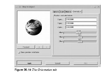
The default center value of the X and Y directions is 0.5. For the Z direction, 0 is the center value (1 is maximal zoom, and negative values is "away from you") there is no limit for the negative scale (but for values under -60 you will probably not see anything). XY controls the Y rotation around the Z axis, YZ controls the Z rotation around the Y axis and XZ controls the Z rotation around the X axis. Box And CylinderThis tab is only available if you choose to map against a box or cylinder. There are several drop-down menus where you can choose a different image for each side of the box, or top/bottom the cylinder. This makes it quite easy to design a very nice box that will look like a real package. For example, with a different end cap on the cylinder, you can create a telescope.
| |
Paper Tile
| |
|
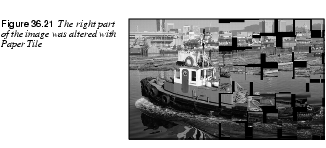
Paper Tile makes your image look like it has been cut into small paper tiles, and then put together in a rather sloppy way, so that a variable gap is formed between each paper tile. This filter is easy to use, and there are only a few options. You set the size and shape of the tiles (in pixels) with the width and height slide bars. Slide determines the size of the largest gap (also measured in pixels), and you can choose between a black or white background. | |
Small Tiles
| |
|
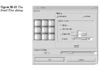
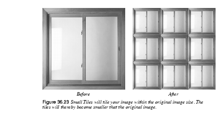
Small Tiles creates a tiled pattern, just as Tile does (see the next section), but it tiles the image within its original size, so the tiled pictures will get smaller. Parameter SettingsThe Segment setting slider controls how many segments/tiles that will be rendered. To create a more convincing pattern, you can also flip tiles both vertically and horizontally. You can flip a single tile with Explicit tile, but you have to press Apply to execute the flip. You can also flip every odd tile (counting from the left) with Alternate tiles. If you check All tiles the flip will affect all tiles. If your image has an alpha channel, you can also set the opacity of your tile. | |
Tile
| |
|
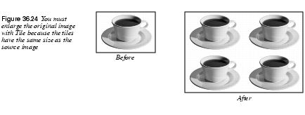
Tile will tile your image according to the size you set (but the new size must be larger than the old for this to work). We recommend that you check the New Image checkbox, because this will leave the original image intact. New Image will create a new, tiled image. An example may clarify how it works: Say that you have a 287x425 pixel image. If you set the new size to 574x850 you will get four original images in the new image. Constrain Ratio makes it easier to make "cleanly" tiled images. | |
![]()
![]()
| Frozenriver Digital Design http://www.frozenriver.nu Voice: +46 (0)31 474356 Fax: +46 (0)31 493833 support@frozenriver.com |
Publisher Coriolis http://www.coriolis.com |
 .
.
 .
.