Modifying Sonar Ranging Modules from Late Model Autofocus Cameras
(simplified interface and multiple echo capabilities)
Jim Remington
The ultrasonic ranging modules in the autofocus cameras made by the
Polaroid Corporation have always appealed to robotics enthusiasts, and
the same basic design has appeared in several different implementations.
All of these function similarly, emitting a short ping at about 50 kHz
upon demand and returning an "echo" ranging signal. The
modules (as salvaged from cameras) are robust, cheap, always seem to work
and there are lots of them available. I can't resist them and have paid
as little as $0.50 for the cameras (which contain several other useful
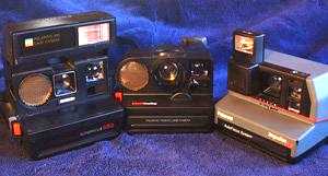
parts) at garage sales. Three basic camera types that are commonly available
in thrift stores or eBay are shown here. Several sources on the Web (for
example
robotprojects.com)
detail modifications required to salvage the modules from the older style
Pronto OneStep (left, center) or similar models, but these modules (right,
top) suffer from limitations such as the requirement that they be powered
down after each ranging cycle. The boards are odd-shaped and contain
shutter and motor drive functions that are not particularly useful for
experimenters.
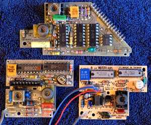
For some years Polaroid has offered a general-purpose ranging module
(Series 6500) and a variety of transducers, but they are still somewhat
expensive. Evidently, Polaroid has recently ceased production of these
boards. Thus, it is worth having a closer look at the ranging modules in
the later model autofocus cameras, such as the "Sun Autofocus 660" or the
less common "Impulse AF" (above, left and right). In these cameras, some
of the camera-specific functions have been relocated to chips on flexible
circuit boards elsewhere in the camera, and the resulting simplified ranging
module looks very similar to the Series 6500 module. However, the internal
circuitry is not the same. The differences reside primarily in the digital
chip (U2) that handles the logic functions and oscillator timing.
In this article I describe in some detail how to remove and modify the
ranging modules from the Sun 660 and Impulse AF cameras, such that they
function identically to the Series 6500 modules. The modified modules do
not require external components for interfacing and have multiple-echo
capabilities. Note: I recently obtained and disassembled one of the the
Polaroid "Spectra" cameras. All that is written below applies to that camera
as well, but "J1" has 17 pins to accomodate the switches added to the board.
Camera Disassembly
In all of these cameras, the internals are located in an intricate snap-together
assembly that slides forward from the case.
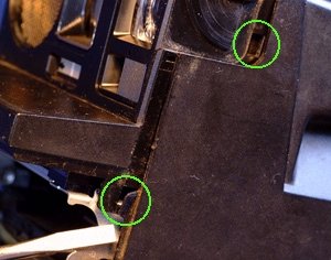
I'll use examples from the Sun 660. Start by opening the film door and
prying at the sides (left) with a flat blade. On the Sun 660, there are
four snap fittings, two on each side (circled). After pulling out the internals,
the ranging module is located in the front shelf of the camera with a shielded
cable connecting to the transducer. It can be popped off by prying aside
the plastic hooks. Pull the flexible printed circuit connector out of the
module and carefully remove the transducer from the camera. (For more detail
on some of these steps, see the nice article on sonar
camera disassembly by Dennis Clark for the Seattle Robotics Society).
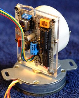
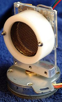
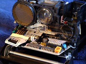
When you are done,you
have the board and transducer shown here. The transducer for the Impulse
AF camera is pretty cheesy (right), but it can be removed from the camera
and used. It does not have convenient mounting characteristics, so I used
instead the instrument-grade transducer from a Pronto OneStep, which works
well with the Impulse AF board.
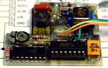
Module Properties.
The modules in the Sun 660 and Impulse AF cameras look like the Series
6500 modules produced by Polaroid but the digital chip (U2, the chip near
the yellow ceramic resonator in the figure at left) has different functions.
The camera connectors, labelled J1, have either 8 (Sun 660, in line) or
9 (Impulse AF, staggered) pins. The pin functions and positions do not
necessarily correspond with J1 of the 6500 series module. "Pin 1" is closest
to the edge of the board.
Pin
"Impulse AF" Function
"Sun 660" Function
1
GND
GND
2
Pin 16 U2 (BLNK)
Pin 16 U2 (BLNK)
3
RC delay, pin 15 U2 (input?)
Pin 15 U2 (BINH)
4
INIT - pin 14 U2
INIT - pin 14 U2
5
Filter
Filter
6
OSC
OSC
7
ECHO (active high, pullup)
ECHO (active high, pullup)
8
Input, diode to pin 15 U2
V+
9
V+
The digital chip (U2) has the same pinout as the Series 6500 chip (TL851),
but with some internal differences. After a couple of hours of experimentation
with an oscilloscope and a computer to drive the board I determined the
following (mostly using the board from the Impulse AF camera, but the Sun
660 seems to behave very similarly):
The digital chip has inputs corresponding to the INIT, BINH and BLNK of
the experimenter module, but only INIT seems to function in the same way.
Put this input high to initiate a "ping".
The ECHO output latches high and the chip must be powered down after each
ranging cycle to reset it. Pin 15, the "BINH" input, if taken high, will
force ECHO low but will not reset the latch. ECHO springs back up immediately
when pin 15 is allowed to go low. The chip will not respond to a further
INIT pulse when latched. Pin 15 may function as BINH before ECHO latches.
The ECHO output is not open collector as in the 6500 Series modules. If
the digital chip is powered down but the ECHO output is kept high by a
pullup resistor (or even by connecting this output to a standard TTL input)
the chip will remain latched up by parasitic power drawn through ECHO!
I was unable to determine the function of the pin 16 of U2 (BLNK on the
TL851), although it does appear to be an input. High or low signals here
have no obvious effect. Both pin 15 and pin 16 do seem to be used, but
differently on the Sun 660 and Impulse AF cameras as evidenced by associated
circuitry.
The OSC output of 93.3 kHz is very useful for ranging. The period of this
oscillator corresponds to about 0.011 foot of travel for the ultrasonic
pulse at room temperature and this eliminates processor-dependent timing
considerations. A microprocessor counter input connected to this output
would simplify coding, as 100 counts = 1 foot (approximately) of there-and-back
travel. Right shift the count by one to get the range in units of 0.01
foot or 3 mm.
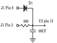
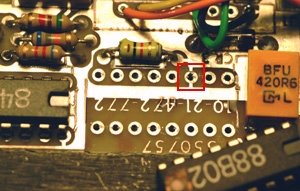
The Impulse AF J1 connector has two connections
to pin 15 of U2 ("BINH") as shown at right.
The Sun 660 and Impulse AF ranging modules can be used without modification
if one is not interested in the BINH or BLNK functions. However, in order
to reset the digital chip in these modules, after each ranging cycle the
module must be powered down as with the older autofocus cameras. One solution,
requiring a bit of extra circuitry, is provided in the article by Dennis
Clark. The disadvantage of this approach is that there must be 3 signal
lines from the controlling microprocessor: PowerUp, INIT and ECHO. A delay
must follow the PowerUp signal for the oscillator to stabilize before INIT
is applied.
Both of these camera boards can be made to function exactly like the
Series 6500 module, which requires only the two signal lines INIT and ECHO
for the simplest applications. This simply involves replacing the digital
chip U2 as follows. One source of these chips (TL851) is Acroname.
Board Modifications
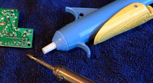
You will need a fine-tipped soldering pencil (30 watts max) and a desoldering
tool. Specialized desoldering tools exist for chips that heat up all the
pins at once, but I use a "solder vacuum", a spring loaded vacuum tool
with a teflon tip.
I also filed down the tip of my 30 watt soldering pencil to make a narrower
point than when purchased.
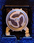
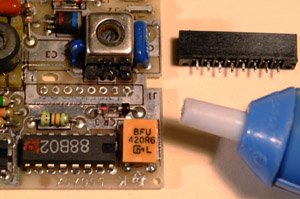
Start by removing the useless connector at "J1". It is possible to remove
it pin-by-pin with a solder pencil and a pair of needlenose pliers, but
using the soldervac will give you necessary practise for the chip removal.
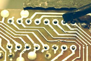
With the board clamped upside down in a vise, heat up each pin connection
until the solder melts and quickly suck up the solder by cycling the pump
and the yellow release lever shown in the figure. It helps to put the white
teflon tip flat as possible on the board, but work quickly!
As shown below, if the pin moves in the hole after this procedure, it is
free. You may have to "pop" it free with a small pointed tool. When all
8 (9) pins have been desoldered, the connector can be pulled out easily
as shown above right.
Board Function Check
Next, check out whether the board functions. Attach the transducer and
wires to J1 at V+, GND and INIT. ECHO is not needed at this point unless
you are curious. If the board doesn't pass this test, it is probably not
worth the effort to desolder and replace U2. However, I have yet to see
one fail in about 6 camera disassembly operations. Apply 5 volts between
V+ and ground, then connect INIT (green lead in figure) to V+. You should
hear a click. This is the transducer ringing after the ultrasonic pulse
has been emitted. Attempts to connect INIT and V+ will not produce further
clicks until the power is cycled off and on again. In the photo,
ECHO (the yellow lead) has been connected to a scope probe for signal verification.
Next, desolder U2. Clamp the board upside down in a vise. With practise,
this takes about 10 minutes (if you are nervous, try removing chips from
a junked circuit board). Note: the Sun 660 modules are double sided and
have "plated through" connectors which are harder to desolder than the
single-sided Impulse AF boards, but the Sun 660s seem to be more readily
available. As each pin is desoldered, test to see if it can be wiggled
with a small screwdriver as shown here (pin 15 of U2).
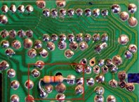
In this case, all of the pins have been successfully desoldered even though
some solder remnants are visible. Sometimes a pin can be popped loose with
a bit of pressure. Avoid overheating the signal traces as they
will break free from the board! If they break or come off, the connections
can usually be repaired with fine wire. I slipped and damaged the trace
above pin 3 of U2, but the board still works. When all pins are loose,
remove the chip by prying gently. Note the ground connection to pin 3 on
the top of the board in the figure at right. Insert a 16 pin IC
socket and solder it to the board. Be sure to inspect the modified board
carefully with a magnifying glass to ensure that there are no solder bridges
between pins or traces. It is a good idea to plug the "old" chip back into
the new socket and retest the board before moving on to the next step.
Proceed to Checkout
Final checkout involves inserting the TL851 chip and checking out the operation.
If you are using the Impulse AF board, some decisions need to be
made about the BLNK and BINH connections. If you do not want to use these
functions, you need not do anything as they will be effectively low. If
you do want to use these functions, take into account the circuit diagram
above that was deduced from the two boards that I looked at. You will probably
need to remove the 80 microfarad capacitor at least. I had originally
removed this capacitor and the 360 ohm resistor connected to pin15 of U2,
thinking that they may have had something to do with the apparent failure
of chip to respond to some inputs, but that was not the case. It is recommended
that if you do not use BINH or BLNK to connect both pins to ground.
Don't forget to put a pullup resistor from ECHO to V+! There is room for
this between the traces on the solder side of the board (Impulse AF module
shown here).
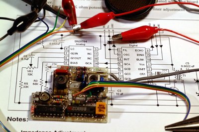
Example Application: Sonar Scanner
Using a pancake style stepper motor salvaged from an old Seagate 20 Mb
drive (4 coils, 85 ohms per phase, 200 steps/revolution) I constructed
a simple sonar scanner circuit similar to one first presented by Steve
Ciarcia in Byte Magazine in November 1980 (a later article by Steve is
reprinted by Micromint).
It works great! (Note the added 470 uF capacitor on the sonar board...
if your 5V power supply is not well filtered, you should have at
least 1000 uF total to handle the up to 2 A peak current the module
draws during the "ping" to avoid causing a serious glitch in V+. I measured
1 amp peak, which is the C5 (.0022 uF) bias charging current, on the Impulse
AF board).
The 12 V stepper motor works well on 5 volts and allows a maximum half-stepped
angular resolution of 0.9 degrees. Since the sonar transducer has a response
pattern that is about 15 degrees wide, the sonar image obtained by the
scanner is a smeared out view of its surroundings. The response pattern
of the detector (the point spread function) is published, so my next project
will be to use image deconvolution to correct for this smearing effect.
Multiple Echo Capabilities
My initial experiments with the scanner described above utilizing the multiple
echo feature were disappointing. The echo detection capability works, but
interpretation of even the second echo can be difficult. In a simple setup
with a few objects on a table, "echos" appeared in what should have
been "empty space". I assume that this is due to multiple reflections between
nearby objects, but it will take some experimentation to sort this out!
It is not clear to me that this feature would be very useful in robotics.
Feel free to email me with comments and/or suggestions.
Impulse AF, Sun 660 and Pronto OneStep are trademarks of the Polaroid
Corporation.
Thanks to Colin Mitchell for help with image compression.
 The
modules (as salvaged from cameras) are robust, cheap, always seem to work
and there are lots of them available. I can't resist them and have paid
as little as $0.50 for the cameras (which contain several other useful
parts) at garage sales. Three basic camera types that are commonly available
in thrift stores or eBay are shown here. Several sources on the Web (for
example
robotprojects.com)
detail modifications required to salvage the modules from the older style
Pronto OneStep (left, center) or similar models, but these modules (right,
top) suffer from limitations such as the requirement that they be powered
down after each ranging cycle. The boards are odd-shaped and contain
shutter and motor drive functions that are not particularly useful for
experimenters.
The
modules (as salvaged from cameras) are robust, cheap, always seem to work
and there are lots of them available. I can't resist them and have paid
as little as $0.50 for the cameras (which contain several other useful
parts) at garage sales. Three basic camera types that are commonly available
in thrift stores or eBay are shown here. Several sources on the Web (for
example
robotprojects.com)
detail modifications required to salvage the modules from the older style
Pronto OneStep (left, center) or similar models, but these modules (right,
top) suffer from limitations such as the requirement that they be powered
down after each ranging cycle. The boards are odd-shaped and contain
shutter and motor drive functions that are not particularly useful for
experimenters.
 I'll use examples from the Sun 660. Start by opening the film door and
prying at the sides (left) with a flat blade. On the Sun 660, there are
four snap fittings, two on each side (circled). After pulling out the internals,
the ranging module is located in the front shelf of the camera with a shielded
cable connecting to the transducer. It can be popped off by prying aside
the plastic hooks. Pull the flexible printed circuit connector out of the
module and carefully remove the transducer from the camera. (For more detail
on some of these steps, see the nice article on sonar
camera disassembly by Dennis Clark for the Seattle Robotics Society).
When you are done,
I'll use examples from the Sun 660. Start by opening the film door and
prying at the sides (left) with a flat blade. On the Sun 660, there are
four snap fittings, two on each side (circled). After pulling out the internals,
the ranging module is located in the front shelf of the camera with a shielded
cable connecting to the transducer. It can be popped off by prying aside
the plastic hooks. Pull the flexible printed circuit connector out of the
module and carefully remove the transducer from the camera. (For more detail
on some of these steps, see the nice article on sonar
camera disassembly by Dennis Clark for the Seattle Robotics Society).
When you are done,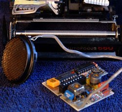
 you
have the board and transducer shown here. The transducer for the Impulse
AF camera is pretty cheesy (right), but it can be removed from the camera
and used. It does not have convenient mounting characteristics, so I used
instead the instrument-grade transducer from a Pronto OneStep, which works
well with the Impulse AF board.
you
have the board and transducer shown here. The transducer for the Impulse
AF camera is pretty cheesy (right), but it can be removed from the camera
and used. It does not have convenient mounting characteristics, so I used
instead the instrument-grade transducer from a Pronto OneStep, which works
well with the Impulse AF board.
 to pin 15 of U2 ("BINH") as shown at right.
 I also filed down the tip of my 30 watt soldering pencil to make a narrower
point than when purchased.
I also filed down the tip of my 30 watt soldering pencil to make a narrower
point than when purchased.
 In this case, all of the pins have been successfully desoldered even though
some solder remnants are visible. Sometimes a pin can be popped loose with
a bit of pressure. Avoid overheating the signal traces as they
will break free from the board! If they break or come off, the connections
can usually be repaired with fine wire. I slipped and damaged the trace
above pin 3 of U2, but the board still works. When all pins are loose,
remove the chip by prying gently. Note the ground connection to pin 3 on
the top of the board in the figure at right. Insert a 16 pin IC
socket and solder it to the board. Be sure to inspect the modified board
carefully with a magnifying glass to ensure that there are no solder bridges
between pins or traces. It is a good idea to plug the "old" chip back into
the new socket and retest the board before moving on to the next step.
In this case, all of the pins have been successfully desoldered even though
some solder remnants are visible. Sometimes a pin can be popped loose with
a bit of pressure. Avoid overheating the signal traces as they
will break free from the board! If they break or come off, the connections
can usually be repaired with fine wire. I slipped and damaged the trace
above pin 3 of U2, but the board still works. When all pins are loose,
remove the chip by prying gently. Note the ground connection to pin 3 on
the top of the board in the figure at right. Insert a 16 pin IC
socket and solder it to the board. Be sure to inspect the modified board
carefully with a magnifying glass to ensure that there are no solder bridges
between pins or traces. It is a good idea to plug the "old" chip back into
the new socket and retest the board before moving on to the next step.
 Don't forget to put a pullup resistor from ECHO to V+! There is room for
this between the traces on the solder side of the board (Impulse AF module
shown here).
Don't forget to put a pullup resistor from ECHO to V+! There is room for
this between the traces on the solder side of the board (Impulse AF module
shown here).